
It's important to find different and challenging avenues of expression and creativity. Photography has been my passion for many years, but sometimes I need to divert from this path and explore new ones. As a computer programmer, technology is my bread and butter. So I am often attracted to creative ways to use technology and innovation.
This is a solar-powered battery system that charges 2 100 amp/hour AGM batteries and can provide up to about 40 amps of current. It was originally intended to run my Christmas lights and decorations, but is now capable of running more than that.
My goals with the development of this system were as follows:
- Provide the necessary power for the small tasks I envisioned to run (Christmas decorations and a few lights.)
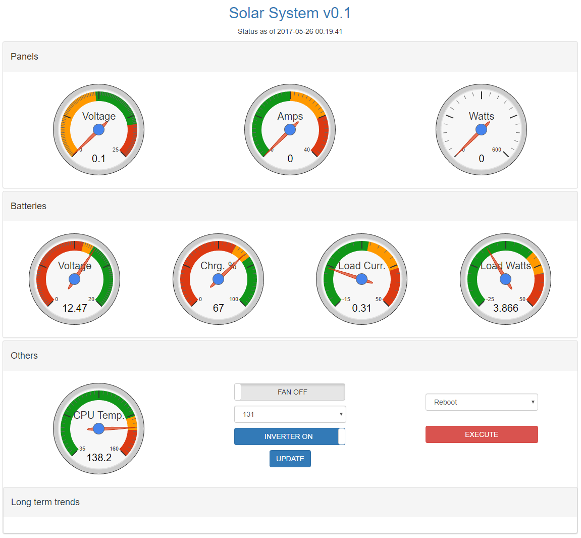
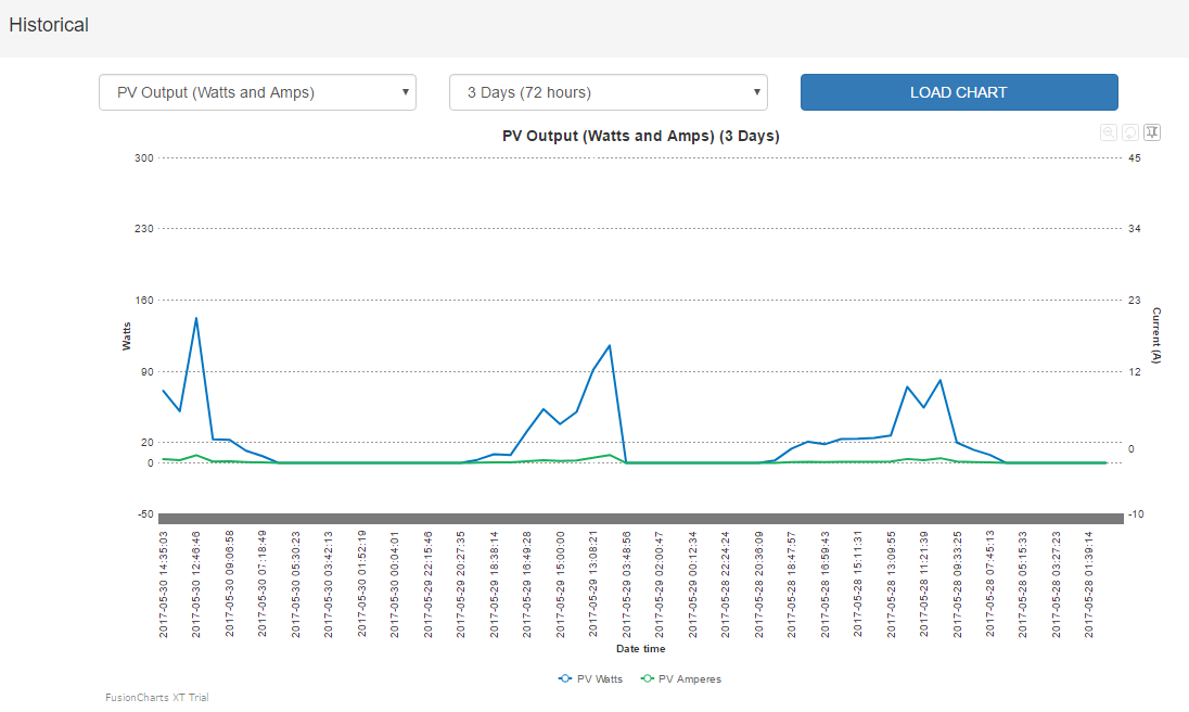
- Provide real-time data of power being collected from the sun, stored in the batteries, and used by the various loads connected to them.
- Control all parts of the system remotely.
- Occupy the least amount of space and in the least conspicuous manner in my small backyard.

Main Components
I've compiled a list of all the parts I used for this project to help you evaluate your own needs if you decide to embark in this enterprise. Hope you find it useful!
Photovoltaic panels
The current setup uses 4 100 watt monocrystalline solar panels from Renogy (https://www.renogy.com/renogy-100-watt-12-volt-monocrystalline-solar-panel/).
Solar Charge Controller
Charge controller is vital to properly charging and maintaining your batteries. I use a 40 amp MPPT (maximum power point tracking) SolarEpic charge controller (https://www.amazon.com/gp/product/B00YCI48F4/ref=oh_aui_search_detailpage?ie=UTF8&psc=1).
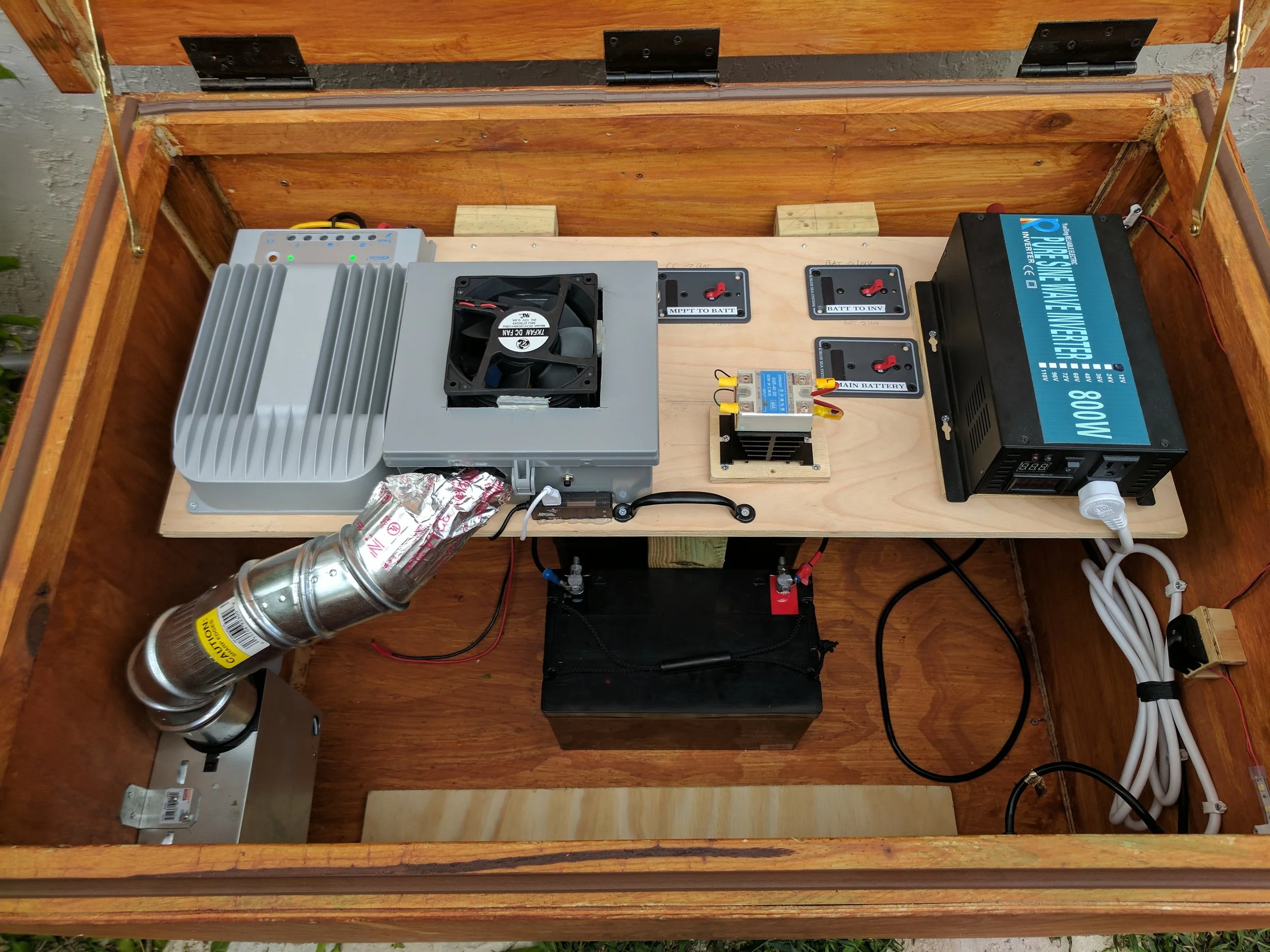
Close up of the batteries, DC to AC inverter, and solid state relay that controls power to the inverter.
Batteries
I currently have two 100 am/hour deep cycle AGM 12 volt batteries (https://www.amazon.com/gp/product/B00S1RT58C/ref=oh_aui_search_detailpage?ie=UTF8&psc=1) connected in parallel to provide 200 amp/hours.
Inverter
The system runs a 800 watt (peak of 1600 watt) pure sine wave 12 volt DC to AC inverter (https://www.amazon.com/gp/product/B0154BQFDU/ref=oh_aui_search_detailpage?ie=UTF8&psc=1).
System Controller
A Raspberry Pi running Raspbian Jessie Lite (https://www.raspberrypi.org/downloads/raspbian/) receives data from the MPPT controller as well as a couple of older Arduino Duemilanove boards. The Arduino boards control a solid state relay that provides power to the inverter and reports back its status to the Raspberry Pi. The other Arduino receives data from a CSLA2CD linear current sensor (https://www.amazon.com/gp/product/B00DKYPYN6/ref=oh_aui_search_detailpage?ie=UTF8&psc=1) monitoring the positive pole of the battery system.
The Raspberry Pi runs off of a 5 volt UBEC adapter (https://www.amazon.com/gp/product/B01GHMW0C0/ref=oh_aui_search_detailpage?ie=UTF8&psc=1) that’s typically used to connect LiPO batteries to remote control model cars and airplanes. It provides ample amperage (up to 3 amps) when the Pi needs it at a very consistent voltage hovering at around 5.2 volts.
Safety controls
Fast acting circuit breakers
I have installed 40 amp circuit breakers (https://www.amazon.com/gp/product/B000MMC8BU/ref=oh_aui_search_detailpage?ie=UTF8&psc=1) between various sections of the system to minimize damage due to overloads or spikes.
Solid State Relay
Power to the inverter flows through a solid state relay (https://www.amazon.com/gp/product/B01EL67LUA/ref=oh_aui_search_detailpage?ie=UTF8&psc=1). This relay is controlled via an Arduino and managed by the Raspberry Pi control system.
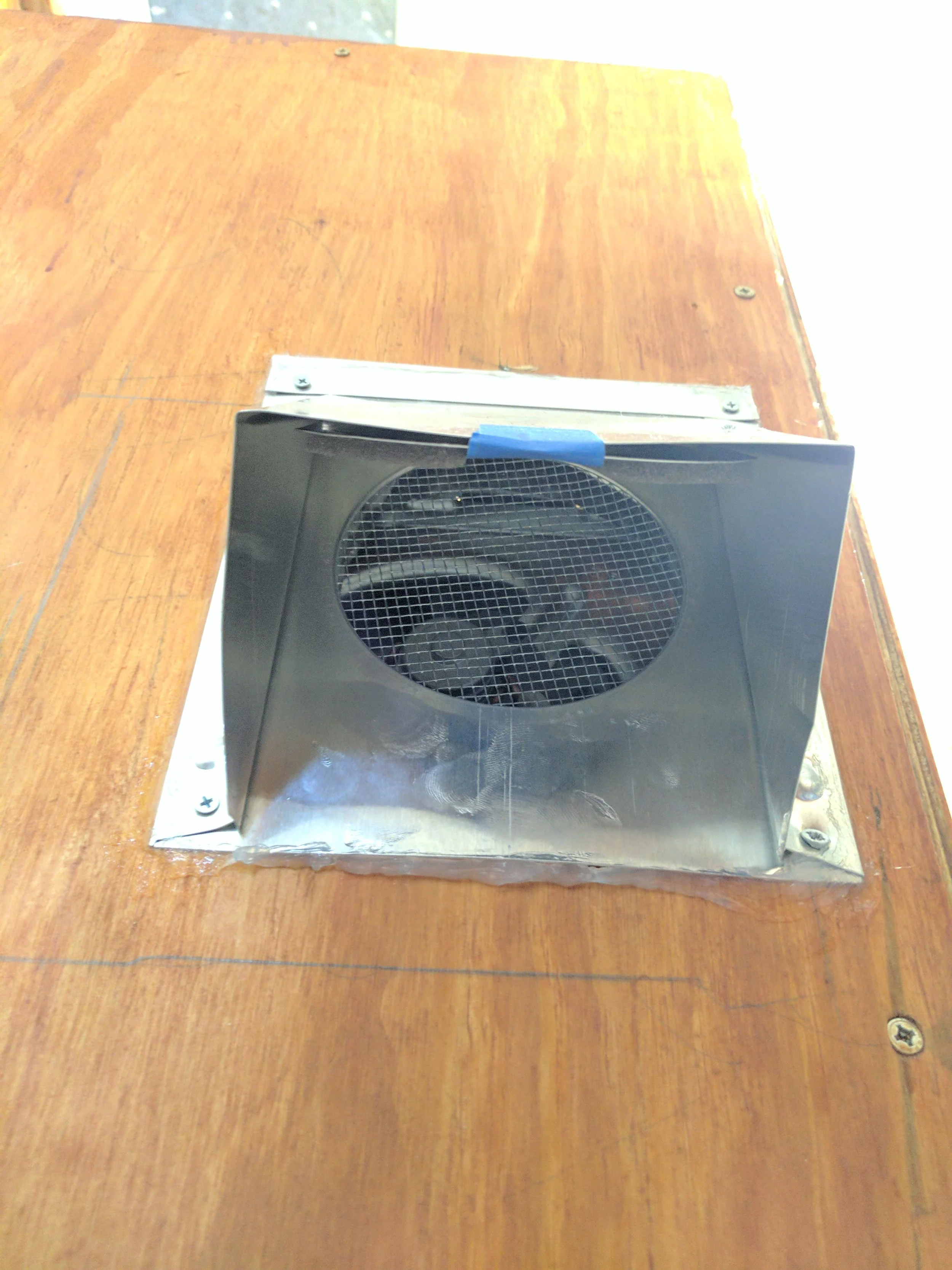
Cooling
Living in Florida I needed to make sure the Raspberry Pi in charge of managing most of the equipment remained cool and relatively free of humidity. Since this system will be in my backyard, I installed a bathroom fan system that runs an AC fan (http://www.homedepot.com/p/NuTone-50-CFM-Wall-Ceiling-Mount-Exhaust-Bath-Fan-696N/100081599) to pull air from the outside of the container. The air flows through aluminum pipes and directly into the container that protects the Raspberry Pi and other circuits. I also installed a smaller DC fan to pull the hot air out of this box and into the larger container area. I use a relay shield (https://www.amazon.com/gp/product/B00E0NTPP4/ref=oh_aui_search_detailpage?ie=UTF8&psc=1) managed from the Raspberry Pi to control when the fans run. They start when the Pi’s CPU temperature reaches a threshold I set. I can also turn off and on the fans via the web interface.

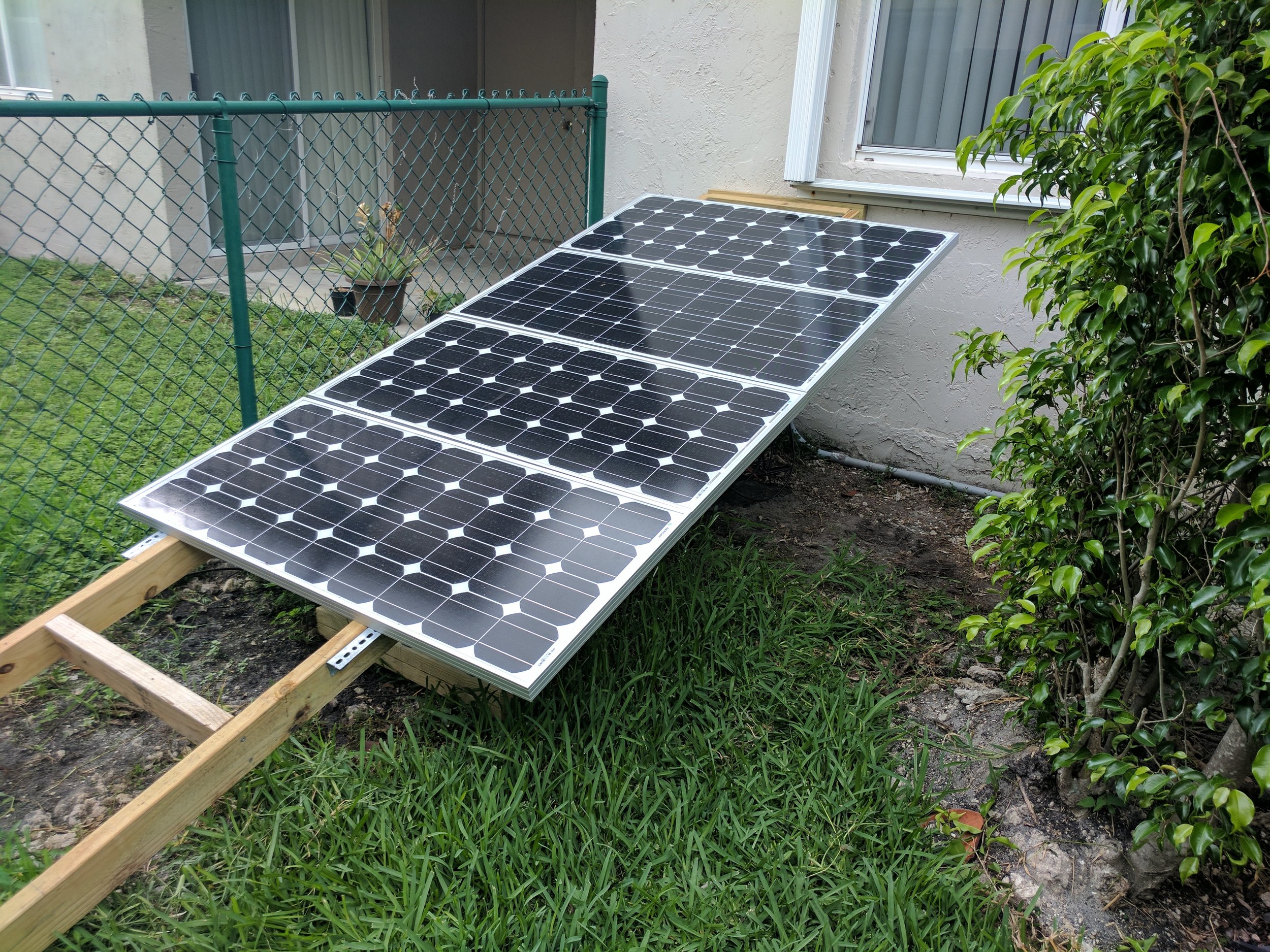
Solar Panel Installation
I used mostly 2 x 4s to create a framing structure to support the panels. I also wanted the ability to tilt them from about 20 degrees to 0 degrees (fully horizontal). All of this needed to happen in a very small area away from wondering eyes.

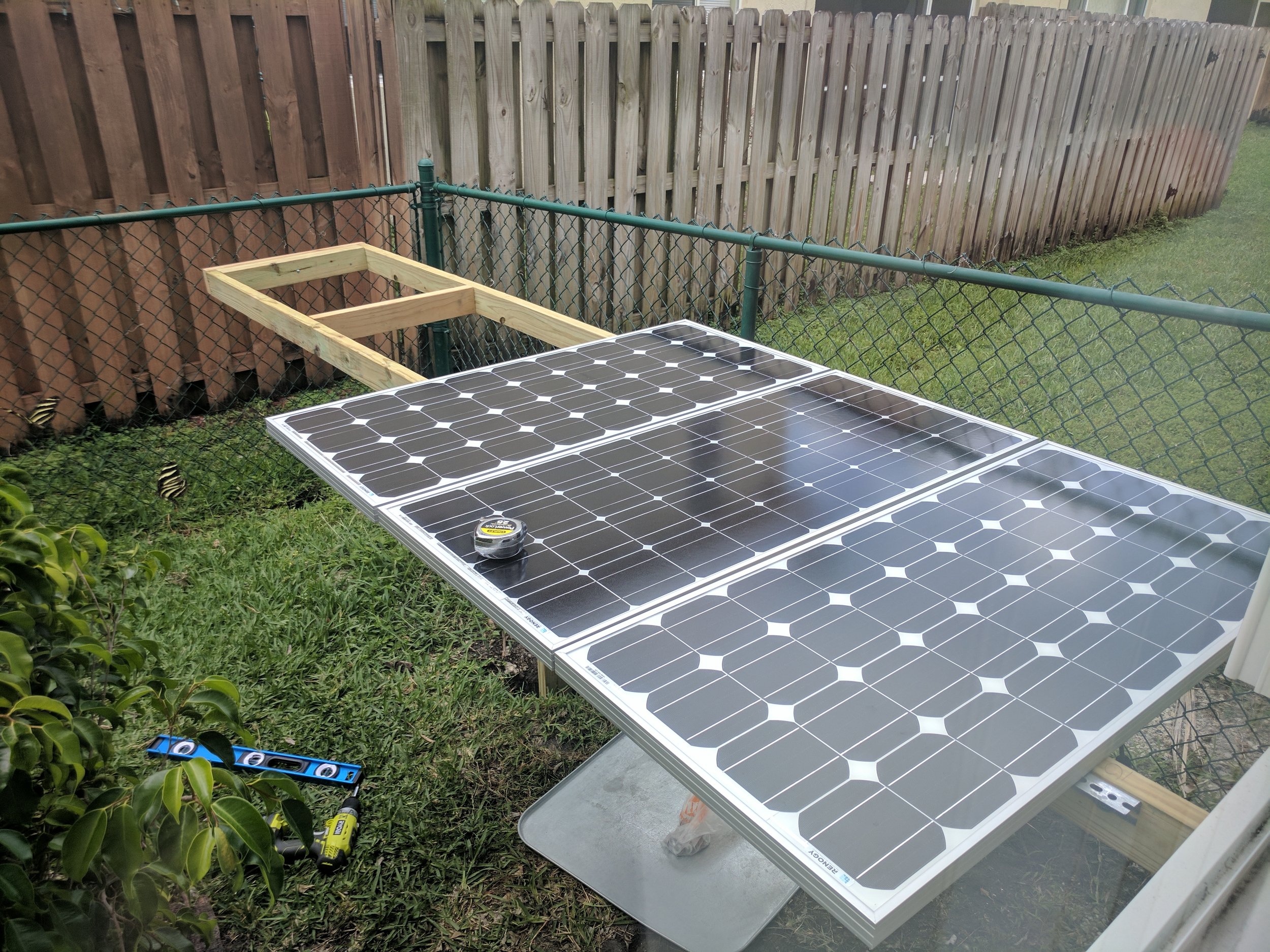


I used Everbilt slotted angles to attach the panels to the wood. To protect the panel's aluminum framing I used rubber sheets and cut to the size so the aluminum wouldn't touch the slotted angles as I read that the aluminum, if scratched or broken, may rust and fall apart.
The area I allocated for the panels may hold a total of 6. I am thinking that the top of the container may be able to hold a 7th one. For now, though, I am sticking with 4.
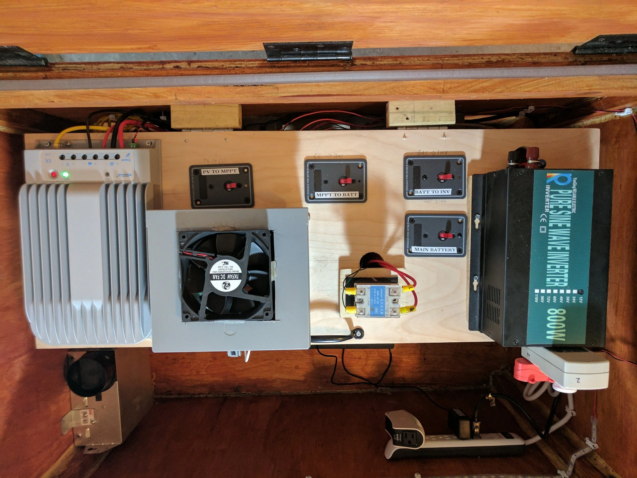
System Infrastructure
System schematic.
Panels to Charge Controller
The panels are connected in parallel to keep voltage at about 12 volts and increase the amperage. These are connected to a 40 am fast acting circuit breaker on the positive cable and then on to the MPPT controller.
Controller to Batteries
The controller then connects to the batteries via another 40 amp breaker. The breaker then has wires connected to the terminal blocks which then connect to the batteries.
The batteries are connected in series as well thus doubling their amp/hour rating.
I decided to have all power connections end in terminal blocks rather than on the batteries directly. This helped me organize my connections more neatly and also gave me the added benefit of more easily controlling when power to and from the batteries could occur. I added another breaker between the positive end of the batteries and the positive terminal block to enable this control. I also added the current sensor right at the terminal block area to monitor the current flowing from and to the battery.
Batteries to Inverter
These two are connected directly via their negative terminals. The positive terminal from the battery connects to a 40 amp breaker and then to a 40 am solid state relay. The relay is controlled by an Arduino board which is connected to the Raspberry Pi via USB. The Arduino is programmed to turn on or off power to the relay and thus opening or closing the circuit from the battery to the inverter. On the Raspberry Pi I have a python script running on the background and monitoring commands coming from the web interface to open or close the circuit. It also polls the Arduino board to know what state the relay is on.
Yellow line signifies the USB connection between the Pi and Arduino. Also note the presence of a 47 micro farad capacitor between the Arduino's reset pin and ground. This is to prevent the Arduino from resetting every time a serial connection is established.
Powering the Arduino to control the relay is done via the 12 volt battery system itself and not through the Pi's USB connection. I noticed that the Pi consumed less power (amperage requirement dropped) when the Arduino had its power supplies from the batteries. This arrangement made the Pi more stable.
Raspberry Pi as the Control Center
The Raspberry Pi plays several important roles in the data acquisition, storage, and management of the whole system:
Reading Data from the Charge Controller
Thanks to the great documentation I found at the Solar Powered Home website, I was able to decipher the data coming from the MPPT controller via its RS485 interface. I won't repeat what the author explained. Make sure tom visit his site; it's worth it! I have taken part of his scripts in Python and adjusted them to fit my needs.
Reading Data from the CSLA2CD current sensor
The sensor is connected to another Arduino and sends data back to the Raspberry Pi via the USB interface.


The current sensor returns half of the voltage it receives when there is zero current, as the sensor detects changes in the magnetic field near the source of current (the positive wire from the battery to the terminal block) the signal voltage changes. The Arduino receives this voltage in its analog pin and converts it to a value between 0 and 1023. I had to use a voltage divider to bring the voltage down from 6 volts to 3 so it the analog pin could handle it.
This Arduino is also powered directly from the 12 volt batteries. However, because their voltage changes so radically, the data I receive from the sensor is erratic and not very accurate. I will need to add a voltage regulator to stabilize the voltage being fed to the sensor in order to receive usable data.
The Raspberry Pi is also connected to the 12 volt batteries for power. To regulate the voltage down to 5 volts, I used a a UBEC (Universal Battery Elimination Circuit). This little device is able to provide the Pi with ample current to drive the relays and sensors it is connected to. I tried several types of step-down switching and non-switching regulators and fond the UBEC to be the most reliable.
Controlling The Fans and The Solid State Relay
A couple of python scripts are constantly running on the background monitoring the database for changes to a settings table that stores whether the relay should be open or closed, if the fans should be allowed to run, and if so, at what temperature should they start.
Storing and Publishing All Data
I use MySQL as the database to store all data coming from the sensors and the charge controller as well as some settings to handle the whole system. My code will be available on my Github page.
The data is also shared with my Home Assistant home automation system so I can incorporate this information with all my other home data points using the MQTT messaging system. My Solar System publsihes MQTT topics with all the data obtained from the MPPT controller, relay, current and temperature sensors. I can quickly view it all from my phone.

Source Code
I will make all my code available through my Github site at https://github.com/andres-leon/solar-system.
Credits and Thanks
Much of what I was able to accomplish is thanks to the information provided in the following links:
- Solar Powered Home: http://www.solarpoweredhome.co.uk/
- http://www.cleavebooks.co.uk/scol/calrtri.htm
- Wiring the current sensor (https://images-na.ssl-images-amazon.com/images/I/4106fbDZCDL.jpg)
- Installing MySQL http://raspberrywebserver.com/sql-databases/using-mysql-on-a-raspberry-pi.html
- Handling serial events in the Aduino (https://www.arduino.cc/en/Tutorial/SerialEvent)
- Learning about voltage dividers, Stack Exchange to the rescue! (https://arduino.stackexchange.com/questions/38076/using-voltage-divider-to-read-voltage-from-sensor)
- USeful information on the current sensor (https://openenergymonitor.org/forum-archive/node/10337.html)
- This website sells a kit containing the current sensor. The diagram helped me understand the pins of the sensor itself (http://measure-current.com/?page_id=34)
- The Pymodbus library is what allows the Pi to collect data from the MQTT controller (https://github.com/riptideio/pymodbus)